
Cyberphysics - a web-based teaching aid - for students of physics, their teachers and parents....

- BiologyDiscussion.com
- Follow Us On:
- Google Plus
- Publish Now


Top 13 Experiments on Transpiration | Plants
ADVERTISEMENTS:
The below mentioned article includes a collection of thirteen experiments on transpiration.
1. Experiment to demonstrate the transpiration phenomenon with the bell jar method:
Requirements:
Bell jar, well-watered potted plant, rubber sheet, glass plate, Vaseline.
1. Take a well-watered, healthy potted plant and cover the pot with the help of rubber sheet. Only aerial parts of the plant should remain uncovered.
2. Keep the potted plant on a glass plate and cover it with a bell jar (Fig. 21).

3. Apply vaseline at the base of the bell jar to prevent the outer air to pass in the bell jar.
4. Keep the whole apparatus in light and observe for some time.
5. Set another experiment exactly in the same way except that the pot should be without any plant.
Observations:
Water drops appear inside the wall of the bell jar containing a potted plant while there is no drop in the another bell jar which is without any plant.
Because water drops appear only in the bell jar in which pot is having a plant with its only aerial parts exposed, so it can be concluded that these drops appeared due to the process of transpiration from the aerial parts of the plant. The same can also be concluded by the observations of the control apparatus, in which no water drop appears due to the absence of plant in the pot.
2. Experiment to demonstration of Transpiration by Cobalt-Chloride Screen:
Filter paper, cobalt-chloride solution, a potted plant, clip.
Experiment:
Some pieces of the filter paper are dipped in cobalt chloride solution and then dried off. They are blue coloured. Now, two such pieces of filter paper are taken and pressed on both the surfaces of the leaf of a potted plant with the help of a clip. This apparatus is kept for some time as such.
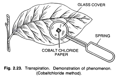
Observation:
After a few hours, when it is observed, the cobalt chloride paper of the lower surface of the leaf becomes pink coloured.
Explanation:
The dried blue coloured cobalt chloride paper turns red as it becomes moist. The stomata are confined mostly on the lower surface of the leaf, and therefore, the cobalt chloride paper of that surface becomes moist and turns red. The paper of the upper side of the leaf may also become pink to some extent, as few stomata are found on this side.
3. Experiment to demonstration of Transpiration by Four-Leaf Experiment:
Four leaves, Vaseline and a string.
To demonstrate the transpiration from the leaf surface, four banyan leaves are taken. Both the surfaces of the A leaf, lower surface (with stomata) of B leaf, upper surface (without stomata) of C leaf are vaselined. The Vaseline is not applied on the D leaf. Now, as shown in the figure the leaves are hanged so that they may transpire freely.
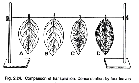
Observation and Explanation:
When the observations are taken after a day or two, they are as follows — the A leaf, which is vaselined on its both the surfaces, looks fresh and green, as no surface transpires. The B leaf is vaselined on its lower surface (with stomata), and transpiration takes place only from the upper surface which is negligible. This leaf also remains turgid and green like the A leaf.
If few stomata are present on the upper surface of the leaf, then it shrivels to some extent. The C leaf is vaselined on its upper surface, which contains less number of stomata or no stomata. The transpiration takes place from the lower stomatal surface, and the leaf shrivels to a large extent.
The D leaf is not vaselined and both the surfaces transpire freely releasing much water. The leaf wilts completely in this case. This experiment proves that the rate of stomatal transpiration is fairly higher than the cuticular transpiration.
4. Experiment to Compare the rate of transpiration from both the surfaces of leaf by Garreau’s Potometer:
Garreau’s potometer, stand, leaf, etc.
With the help of this apparatus, the comparative study of the transpiration from both the surfaces of the leaf is being done. This apparatus consists of two small bell-jars, which are kept together in close contact as shown in the figure.
A leaf of a potted plant is kept in between these two bell-jars. In each of these bell-jars a small test tube is kept. Each small test tube contains equal amount of anhydrous calcium chloride (CaCl 2 ).
The apparatus is made air-tight, applying vaseline where they press the leaf in between. There are two manometers at the two ends of the bell-jars. They are partially filled with oil.
These manometers, however, maintain the vapour of the bell-jars. If the surface of the oil, within the manometers changes, then it indicates that the apparatus is not airtight or the vapour released from the leaf surface is not completely absorbed by calcium chloride.
The complete apparatus is fitted upon a vertical stand. After few hours, the calcium chloride tubes are taken out and weighed again. This way, the water transpired from both the surfaces of the leaf may be known.
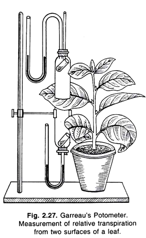
The amount of water transpired from the lower surface (stomatal surface) of the leaf is always greater, as it bears large number of stomata. The cuticular transpiration takes place from the upper surface of the leaf, which is very much less.
5. Experiment to measure the rate of transpiration by using simple potometer or Darwin’s potometer:
Simple potometer, beaker, scale, water, cork, a freshly cut twig, grease, stop watch.
Simple Potometer:
It is made up of glass tube having a side limb. The mouth of the side tube is fitted with a cork having a hole, through which the twig is inserted in the tube. Upper end of the straight tube is closed by a cork and in its lower end a cork with a capillary tube is fitted. Lower part of the capillary tube is placed in beaker containing water. A scale is fitted on the capillary tube (Fig. 29).
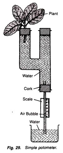
1. Fill the potometer with water and insert a freshly cut twig in the hole of side limb in such a way that its lower end is in the water. Cut the twig in the water.
2. Make all the joints air-tight by applying grease.
3. Insert a bubble in the capillary tube and place the whole apparatus in light.
4. Note the readings in shade, wind and also in darkness.
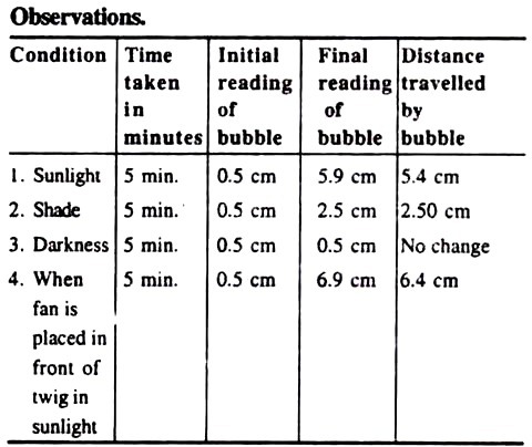
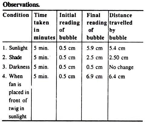
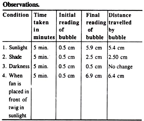
The observations of above table indicate that the largest distance is travelled by the bubble in a given time when the apparatus is placed in front of a fan in sunlight and the distance travelled is least in the shade. There is no change in the position of bubble when the apparatus is placed in darkens.
Changes in all these conditions can be explained as follows:
1. In sunlight:
When the apparatus is placed in sunlight, the stomata will open and the temperature will also be high. So the atmospheric humidity will be less. All these conditions favour the transpiration and so more water will be transpired, and nearly equal amount will be absorbed from the potometer. This can be observed by the movement of bubble in the capillary tube.
2. In shade:
The atmospheric humidity is high in the shady conditions and so the atmosphere outside the apparatus is saturated with water vapours. In the high atmospheric humidity the temperature will also not be too high. All these conditions are unfavourable for the transpiration, and hence it will be too less.
3. In darkness:
Stomata do not open in darkness. So, when the stomata, the chief apparatuses for transpiration, remain close, question does not arise of transpiration and hence there will be no change in the position of the inserted bubble.
4. When the apparatus is placed in front of fan in the sunlight:
Sunlight is in itself sufficient for high transpiration because it increases the temperature, lowers the atmospheric humidity and opens the stomata, being all these conditions favourable for the process.
If a fan is also placed in front of apparatus if will provide a continuous current of wind which also removes the water vapours and reduces the atmospheric humidity, and thus ultimately favouring more for the process of transpiration. Thus, the transpiration process will be very high in these conditions.
6. Experiment to measure the rate of transpiration by using Farmer’s Potometer:
Farmer’s proto-meter, beaker, water, cork, fresh twig cut in water, grease, stop watch.
Farmer’s photometer:
It consists of a wide-mouthed bottle fitted with a rubber cork having 3 holes. In one hole is fitted a thistle funnel provided with a stop cork; through the second hole is inserted a leafy twig; and in the third hole is fitted a bent tube of narrow bore provided with a scale. The other end of the bent tube is placed in a beaker containing water (Fig. 30).
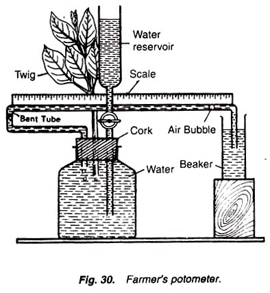
1. Fill the whole apparatus with water and insert a freshly cut twig through one of the holes.
2. Make all the joints air-tight by applying grease, thoroughly.
3. Insert one air bubble in the graduated tube, place it again in the beaker containing water and keep the whole apparatus in light.
4. Note the initial and final readings of the bubble in a given time.
5. Note the same readings in the same time in shade, darkness and by placing a fan in front of apparatus.
7. Experiment to measure the rate of transpiration by using Ganong’s potometer:
Ganong’s potometer, twig, water, beaker, grease, stop watch.
Ganong’s potometer:
It consists of a graduated tube dipped into the beaker containing water. The graduated tube is connected with a vertical arm bearing a cork on its mouth. The cork contains one hole through which a twig is inserted in the water of the vertical arm. Vertical arm is also attached with a stop cork connected with a water reservoir (Fig. 31).
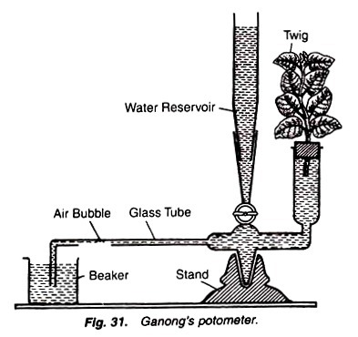
1. Fill the apparatus with water through the water reservoir.
2. Insert a freshly cut twig in the water of the vertical arm through the hole of the cork.
3. Make all the joints air-tight by applying grease.
4. Insert an air bubble in the graduated tube and keep the whole apparatus in sunlight.
5. Note the initial and final readings of the bubble in given time in different conditions like sunlight, shade, darkness and by placing the plant in front of a fan in sunlight.
8. Experiment to measure the rate of transpiration by using Bose’s potometer:
Bose’s potometer freshly cut twig (in water), water, beaker, grease, stop watch, oil.
Bose’s Potometer:
It consists of a wide-mouthed bottle, the mouth of which is fitted with a two-holed cork. The bottle is filled with water. A freshly cut twig is inserted in one of the hole. Through the another hole is fitted a bent tube having two bulbs. A small oil drop is introduced in the outer bulb of the bent tube (Fig. 32).
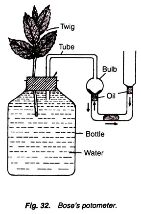
1. Fill the bottle with the water and insert the freshly cut twig in one of its hole.
2. Make the apparatus air-tight by applying grease on the joints.
3. Put a drop of the non-volatile oil in the outer bulb and keep the whole apparatus in light.
The twig is transpiring the water vapours from its leaves and it is also absorbing water from the bottle, thus creating a vacuum. Due to this, the oil drop is pushed towards the inner bulb through the horizontal arm. As soon as it reaches the inner bulb, it bursts and again moves back into the horizontal tube. This movement is again repeated into the inner bulb from the horizontal tube.
Note the time taken for two consecutive bursts with the help of stop watch.
Note the same readings in different conditions, i.e., shade, darkness and by placing the plant in front of fan in sunlight.
Transpiration is highest when the plant is placed in sunlight in front of fan and it is lowest or absent in darkness.
9. Experiment to demonstrate the water-lifting power of transpiration process:
Beaker, water, mercury, stand, capillary tube, vaseline, cork, plant twig, oil cloth.
1. Take some amount of mercury in the beaker and invert a wide-mouthed capillary tube over it.
2. Fill the capillary tube with water.
3. Insert the plant twig into the hole of the cork in such a way so that its cut end is dipped in the water.
4. Apply the vaseline on the cork and hole to make it air-tight (To make the cork region air-tight oil cloth may also be used instead of vaseline).
5. Keep the whole apparatus in sun.
6. Note the mercury level in the capillary tube and wait for some time.
Mercury level rises in the capillary tube (Fig. 16).
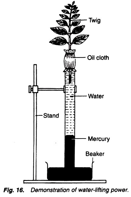
Mercury level rises in the capillary tube because of the pull or suction exerted by the transpiration process. Aerial parts of the plants are continuously evaporating water because of transpiration process. To compensate this loss the water is absorbed by the plant and lifted. So, the space in the capillary tube, which was first occupied by this absorbed water, is now occupied by the mercury. This demonstrates the water-lifting power of the transpiration process.
10. Experiment to demonstrate the suction and to measure suction force due to transpiration:
h-shaped three-limbed tube, capillary tube, beaker, stand, cork, mercury and a small entire plant with roots, stem and leaves.
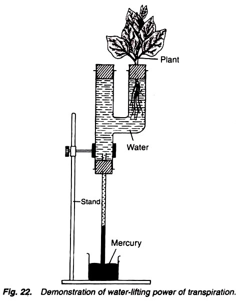
1. Take a h-shaped three-limbed tube and fix it with a stand with the two limbs of the tube up as shown in Fig. 22.
2. Now in the lower limb of tube fit a cork fitted with a capillary tube.
3. Take some mercury in the beaker and keep in it the lower end of the capillary tube.
4. Fill the tube completely with water.
5. Fit a cork tightly in the straight end of the tube. Fit a cork, fitted with an entire small plant, in the another arm of the tube (Fig. 22).
6. Make the apparatus air tight, keep it in the sunlight and observe continuously for some time.
Mercury level in the capillary tube rises.
The rise in the mercury level is due to the fact that water is continuously evaporating from the aerial parts of the plant under the process of transpiration and on the other hand this loss of water is compensated by water absorbed by the roots. Because the roots are absorbing the water from the tube so the space in the capillary tube which was occupied previously by absorbed water is now occupied by the mercury due to the suction force.
This suction force can be estimated by the following formula:
Suction or pulling force = πr 2 h x 13.6 gms
r = radius of capillary tube
h = rise of mercury level
13.6= is the relative density of mercury.
11. Experiment to compare the rate of absorption with the rate of transpiration:
A wide-mouthed bottle with a graduated side tube, cork, oil, a small rooted plant, water, physical balance, weighing box.
1. Take a wide-mouthed bottle fitted with a graduated side tube.
2. Fill the apparatus with water.
3. Just above the water level, in the side tube, put a few drops of oil. It checks the evaporation of water.
4. In the mouth of the bottle fit a cork having a hole. Fix air-tightly a well developed rooted plant in the hole of cork in such a way that its roots remain in the water (Fig. 23).
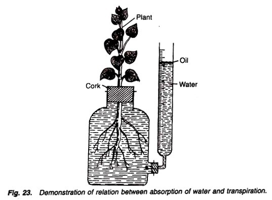
5. Mark the initial water level in the graduated side tube and weigh the whole apparatus.
6. Keep the apparatus in light for some time, note the final level of water in the graduated tube and again weigh the whole apparatus.
The final weight of the apparatus decreases and there is also a decrease in the water level in the graduated side tube.
The difference between the initial and the final weight is equal to the amount of water evaporated under the process of transpiration. The difference in the initial and final water level in the graduated side tube is equal to the water absorbed by the plant.
The difference in the weight of apparatus is nearly equal to the difference in the water level in the graduated side tube, and this indicates the fact that water transpired by the plant is approximately equal to the water absorbed by the plant.
12. Experiment to compare the transpiration rate of lower and upper surfaces of leaf by bell jar method:
Narrow bell jars (2), small tubes (2), anhydrous calcium chloride, stand, potted plant, U- tube, glycerine, mercury.
1. Take two narrow bell jars and fix them on the two sides of a dorsiventral leaf of a potted plant.
2. Connect the bell jars with a clamp stand.
3. Keep a pre-weighed small tube containing anhydrous calcium chloride in each bell jar.
4. Connect one U-tube containing mercury or glycerine at the two ends of bell jars (Fig. 25).
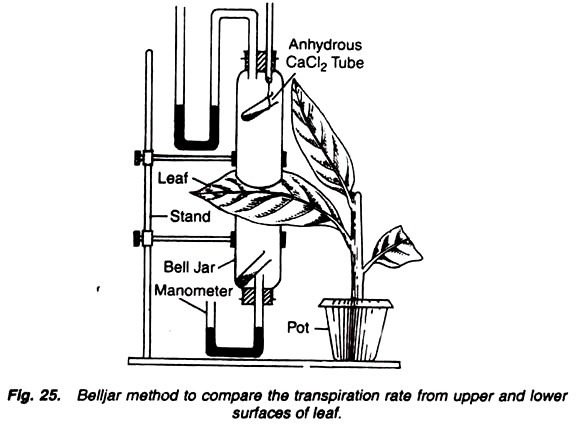
5. Apply vaseline on the contacts between bell jars and the leaf to make the apparatus air-tight.
6. Keep the apparatus as such for a few hours. Remove both the calcium chloride-containing small tubes and weigh them again immediately.
7. Same experiment can be repeated with the other leaves of the same plant as well as the leaves of different plants, to be compared for rate of transpiration from upper and lower surfaces of leaves.
The weight of both the tubes increases. If a comparison is made then it is observed that weight of the lower tube increases more than the weight of the upper tube.
The weight of both the tubes increases because the water vapours are transpired from both the surfaces of the leaf and the same transpired water is absorbed by the anhydrous calcium chloride of the tubes, and hence shows an increase in their weight.
More increase in weight of the tube placed in the lower bell jar than that of the upper bell jar indicates that more water is transpired from the lower surface than the upper surface of the leaf. Side by side it also indicates that in the same area of leaf, more number of stomata are present on the lower surface than that of the upper surface.
13. Experiment to demonstrate that there is a loss in the total weight of plant due to transpiration:
1. Spring balance (2), two leaves of almost equal size, test tube (2), water, vaseline and stand.
1. Take two test tubes filled with water and close their mouth with a cork having a hole.
2. Insert the petiole of both the leaves, one in each test tube, and note that it is dipped in water.
3. Apply vaseline on both the surfaces of leaf ‘B’.
4. Connect both the spring balances with the stand and hang both the tubes on the hook of spring balances (Fig. 27).
5. Make both the corks air-tight by applying vaseline.
6. Note the weight of both the tubes.
7. Put the whole apparatus in light and wait for a few hours. Note the weight of both the tubes again.
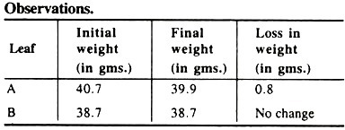
It is observed that there is a clear loss in weight of test tube having leaf ‘A’ and there is no change in weight in leaf ‘B’.
Loss in the weight of leaf ‘A’ indicates that this is due to the process of transpiration because the leaf is continuously transpiring the water vapours. But on both the surfaces of leaf ‘B’ vaseline has been applied and so the leaf is not transpiring and so there is no change in its weight. These results clearly indicate that during the transpiration there is a loss in the total weight of the plant.
Related Articles:
- Transpiration and Absorption (With Diagram) | Plants
- Experiments on Transpiration in Plants | Botany
Experiment , Botany , Transpiration , Experiments on Transpiration
- Anybody can ask a question
- Anybody can answer
- The best answers are voted up and rise to the top
Forum Categories
- Animal Kingdom
- Biodiversity
- Biological Classification
- Biology An Introduction 11
- Biology An Introduction
- Biology in Human Welfare 175
- Biomolecules
- Biotechnology 43
- Body Fluids and Circulation
- Breathing and Exchange of Gases
- Cell- Structure and Function
- Chemical Coordination
- Digestion and Absorption
- Diversity in the Living World 125
- Environmental Issues
- Excretory System
- Flowering Plants
- Food Production
- Genetics and Evolution 110
- Human Health and Diseases
- Human Physiology 242
- Human Reproduction
- Immune System
- Living World
- Locomotion and Movement
- Microbes in Human Welfare
- Mineral Nutrition
- Molecualr Basis of Inheritance
- Neural Coordination
- Organisms and Population
- Photosynthesis
- Plant Growth and Development
- Plant Kingdom
- Plant Physiology 261
- Principles and Processes
- Principles of Inheritance and Variation
- Reproduction 245
- Reproduction in Animals
- Reproduction in Flowering Plants
- Reproduction in Organisms
- Reproductive Health
- Respiration
- Structural Organisation in Animals
- Transport in Plants
- Trending 14
Privacy Overview

Build a Vacuum Chamber

Introduction: Build a Vacuum Chamber

In this Instructable, you will learn how to build your own vacuum chamber using common tools, a vacuum pump, and a few inexpensive or easy-to-locate materials. I suggest reading the entire Instructable before beginning this project , simply so that you will have a better idea of what the finished product should look like. I have written instructions to guide you around making significant mistakes, all of which I learned the hard way. :) Hopefully, this will make building your vacuum much simpler and stress-free.
The items you will need are as follows:
-- a silicone baking mat
-- silicone caulk (and caulk gun)
-- power drill
-- a 1 in thick board of HDPE (high density polyethylene) plastic. This can be ordered for less than $30 bucks.
-- a glass bell jar
-- a vacuum pump (more details later)
-- if needed: detergent-free motor oil
-- 4 plastic soda bottles
-- vinyl tubing, preferably very thin and strong
-- vacuum pressure gauge. A cheap one may be $5-$8
-- vacuum grease
Now... what is a vacuum chamber? What are they useful for? If you are well aware of how vacuum chambers work, and their uses, then by all means skip to the first step.
A vacuum chamber is an area from which the air has been evacuated . The pressure inside the chamber is actually a negative value (i.e. -8.3mmHg, -1Bar, etc.) because the outside atmospheric pressure (about 101,325 pascals or 14.6959 psi) is pushing in on the chamber. In other words, the pressure inside the chamber is far, far less than that outside the chamber. Why is this useful? Well, if all the air is gone then there is no "atmosphere" to interact with whatever you place inside the chamber. Vacuum chambers are used in life sciences to preserve specimens, such as bacteria cultures, in order to store them and keep them from decaying. In physical sciences, the vacuum chamber is incredibly useful in projects involving electricity or optics because the lack of air reduces resistance and interference from gas particles. This helps induce arcing, like what you see on a tesla coil.
Did you know?
The vacuum tube (a small, glass-covered vacuum chamber), was used by Thomas Edison in his invention of the light bulb in 1883 and by Sir John Ambrose Flemming in his invention of the diode in 1904.
Step 1: Create a Seal

In this step, you will need the silicone baking mat, a pen or sharpie, silicone caulk, and the bell jar. You may also want to grab some wax paper or foil and a big, heavy book.
The baking mat you can buy at Hobby Lobby or a home/kitchen goods store. It will be used to make the seal. For the silicone caulk, be sure it is actual silicone.
A few notes on the bell jar... make sure that it is actually a bell jar, as in a glass jar with a rounded dome on top. A cake dome would also work. It is important that the top of the jar be convex because this structure is stronger and will withstand the pressure pressing inwards better. If you use a regular canning jar, for instance, the bottom may curve inwards. This concave structure runs the risk of breaking under pressure and collapsing on itself.
Now, to begin the seal. Trace the rim of the jar onto the baking mat twice, spaced apart, on the right and left sides. Draw an inner circumference and an outer circumference for both circles, about half an inch away from the original circles. Now, cut out both circles along the inner and outer circumferences so that you have two baking sheet rings.
Apply a generous ring of caulk around the top of one of the baking mat rings and place the other baking mat ring on top. You want to apply pressure to adhere the rings together as evenly as possible . A good way to do this is to place a sheet of aluminum foil/wax paper on a table, put the silicone rings on top of that, then another sheet of foil/wax paper, and finally, on top a nice big, heavy book. Do not try to flatten the rings together manually, or you will end up with a bumpy seal that destroys your vacuum.
Let the silicone caulk dry, and then you can trim off any excess with scissors. Consider yourself warned, the silicone caulk is smelly.
This double-thick silicone baking mat ring will be the seal for your chamber.
Step 2: Attach Seal to Plastic Base

In this step, you will need your seal, the 1" thick board of HDPE (high density polyethylene) plastic, a sharpie, and the silicone caulk.
Place your seal on top of the HDPE. Position it so that it is in one corner on the top of the board, so that two of the sides of the board are tangent with the outside edge of the seal. Trace the seal with a sharpie.
After removing the seal, Apply a generous ring of caulk to the board between the sharpie lines. Place the seal back on top. Like you did before, put a piece of aluminum foil on top and a big heavy book on top of that. Let dry.
If you want you can use your finger to smooth out the excess caulk along the edge of the seal. Your seal should be as flat and smooth as possible, and be sealed to the board on all sides.
Step 3: Drill Tunnels in Base & Insert Tubing

In this step you will need a power drill, vinyl tubing, and silicone caulk. The vinyl tubing should be pretty small and strong. I used the vinyl tubing that goes with a nebulizer, because I had extra.
Get out your power drill and drill bits.The drill bit you should use should be roughly the size of the vinyl tubing.
Mark a point inside the seal on the top of the board. From the 1" thick side of the board, drill through the plastic until the tip of the drill is underneath the point on the top. It is a good idea to measure the drill bit and the distance to the point from the side of the board, so that you have a good idea of how far in you need to drill.
Drill from the top point down into the tunnel from the side. The two tunnels should open into each other. It is very, very important not to drill all the way through the plastic while drilling downwards.
On the 1" thick side of the board where you drilled in through the side, drill two more holes on either side. For these holes, drill diagonally into the center hole. These tunnels should open cleanly into each other.
Cut three lengthy pieces of the vinyl tubing. Insert one end of each into the 1" thick side of the board.
Step 4: Create Pressure Release Valves

For this step, you will need 4 plastic soda bottles, scissors, silicone caulk, and the drill. Electrical tape may come in handy.
Using scissors, cut the tops off of 4 plastic soda bottles, just underneath the lip. Make the cut surfaces as smooth as you can.
Use silicone caulk to seal the cut sides of two of the bottle tops together. If you want, wrap electrical tape tightly around the outside to hold them in place and let the silicone dry completely. Be sure that the silicone does not seal up the inside of the bottle tops completely, and that at least one of the screw-on lids is still removable.
Do the same for the other two bottle tops. These attached bottle tops are going to be your pressure valves.
In the cap on one side of each valve, drill a hole through the cap. This is so you can insert the vinyl tubing.
Step 5: Attach Pressure Gauge and Valves

This step will require the vacuum pressure gauge, both pressure valves, and silicone caulk. Electrical tape may prove useful again.
On the ends of each of the three pieces of vinyl tubing, attach the pressure gauge to one, and pressure valves two the other two. Seal the pressure valves to the tubing with silicone.
Attaching the gauge may be a trick because the gauge is probably much wider than the tubing. Just use whatever works that is airtight and can connect the two together. (I used a plastic part that the mask screws onto on the nebulizer tubing.) Electrical tape may come in handy again along with silicone to accomplish this.
Step 6: Attach to Pump and Seal With Caulk

This step will require the vacuum pump, rubbing alcohol, vacuum grease and silicone caulk.
If you do not want to buy vacuum grease, ask around and see if anyone has some you can borrow. You won't need much.
There are three ways to get a vacuum pump if you do not already have one. You could buy one, borrow one, or make one. There are ways of making a vacuum pump out of an old refrigeration compressor or by converting a pancake compressor, but I would recommend researching that elsewhere.
How to attach the vacuum pump may depend upon what your pump is like. Use one of the pressure valves to attach the pump. If the tubing could attach directly, you could cut the pressure valve off entirely. Do whatever is necessary to create an airtight seal between the pump and the tubing.
In order to prepare the chamber to be turned on, clean of the seal on the board with isopropyl alcohol (rubbing alcohol), apply a thin layer of vacuum grease to the bottom of the bell jar, and place the bell jar on the seal. Press down on the bell jar as you turn on the pump.
Air will leak through the space between the tubing and the plastic base. Apply caulk around the tubing on the edge of the board. It is good to do this while the pump is on, because it will slurp the silicone into the small space between the tubing and the plastic. Turn off the pump and let the caulk dry.
Step 7: Checking for Leaks
After the silicone is dry, press down on the bell jar and turn on the pump again. You will now proceed to look for vacuum leaks. This step is critical in getting your vacuum chamber to work!
Observe the reading on the vacuum pressure gauge to see if you are pulling a good vacuum. Check thoroughly for leaks by listening for hissing air and looking for holes. Seal any leaks you find with silicone.
A good way of checking for leaks near or on the tubing is to pinch off areas of the tubing or blocking the hole into the chamber and observing what that does to the pressure shown on the gauge.
Researchers, scientists, and engineers are always battling vacuum leaks. Blocking them is important because even a small vacuum leak can destroy your vacuum.
Step 8: Testing and Applications

Now that your vacuum is all sealed up, turn it on and see how low the pressure will drop on the gauge.
One thing you can do to test your vacuum is place a crushed plastic soda bottle with an airtight lid inside the chamber. As the vacuum is pulled, the bottle should inflate to its original state. Once the vacuum is released, the bottle will crumble again.
A vacuum chamber can be used in loads of awesome science projects and many other things. For example, you could run wires through the base to preform electrical experiments in a vacuum. It certainly helped me!
Happy building!
- Mailing List
- Terms and Conditions
- © Copyright Notice
- All Equipment
- Biology Equipment
- Chemistry Equipment
- Physics Equipment
Bell in a Bell Jar AKA: Vacuum Jar

Consists of a bell jar with a household bell or buzzer suspended inside. A vacuum is created within the jar whilst the bell is ringing. Once a near vacuum has been created, the bell cannot be heard as sound cannot travel through a vacuum.
Related Links
- Vacuum Pump (AKA: Air Pump)

Our Objective
To demonstrate that sound needs a material medium for its propagation.
What is sound?
Sound is a mechanical wave that needs a material medium like air, water, steel, etc., for its propagation. We can describe a sound wave by its frequency, wavelength and velocity. The sound wave is a longitudinal wave, ie., the particles of the medium vibrate in a direction parallel to the direction of the propagation of the wave.
A sound wave needs a medium to travel
A sound wave travels in the form of a longitudinal wave and it requires a material medium for its propagation. Sound always originates from some vibrating body. These vibrations are produced by tuning forks, drums, bells, the strings of a guitar, etc.
Human voice originates from the vibrations of the vocal chords and the sound from the musical instruments is due to the vibrations of the air columns. In some cases, the vibrating frequency of the source may be so very small or so very large that it is not audible to the human ear. The audible frequency ranges from 20 Hz to 20 kHz. The frequency below 20 Hz is called infrasonic and the frequency above 20 kHz is called ultrasonic.
The bell jar experiment is a common experiment used to demonstrate that sound needs a medium to travel.
What is a bell jar?
A bell jar is a laboratory equipment used for creating a vacuum. It is so named as its shape is similar to that of a bell. A bell jar is placed on a base which is vented to a hose fitting that can be connected via a hose to a vacuum pump. By pumping the air out of the bell jar, the air pressure inside the jar can be varied.
How does the experiment work?
The experiment is done by placing an electrical bell in the bell jar. As the air is pumped out of the sealed bell jar, the sound from the bell jar fades. At a particular vacuum, no more sound is heard from the bell, but we can see that the hammer continues hitting the gong and sound is produced. However, the sound is not audible to our ears because of the vacuum inside the jar. This demonstrates that the sound wave cannot travel through vacuum. That is, a sound wave needs a material medium for its propagation.
Learning outcome
We can infer that sound needs a material medium for its travel.
Developed by Amrita Vishwa Vidyapeetham & CDAC Mumbai. Funded by MeitY (Ministry of Electronics & Information Technology)
English हिंदी മലയാളം मराठी

IMAGES
COMMENTS
A bell can be heard ringing within a bell jar. The bell jar is connected to a vacuum pump and the air is slowly removed. Once a vacuum has been achieved the pumped is turned off and air...
This experiment demonstrates that sound waves require a medium (Solid, Liquid, Gas) to transmit.
Experiment to show sound cannot travel through a vacuum. This classic experiment is beautifully illustrated in this mini-vidclip: A bell can be heard ringing within a bell jar. The bell jar is connected to a vacuum pump and the air is slowly removed.
1. Take two narrow bell jars and fix them on the two sides of a dorsiventral leaf of a potted plant. 2. Connect the bell jars with a clamp stand. 3. Keep a pre-weighed small tube containing anhydrous calcium chloride in each bell jar. 4. Connect one U-tube containing mercury or glycerine at the two ends of bell jars (Fig. 25). 5. Apply vaseline ...
Build a Vacuum Chamber: In this Instructable, you will learn how to build your own vacuum chamber using common tools, a vacuum pump, and a few inexpensive or easy-to-locate materials. I suggest reading the entire Instructable before beginning this project, simply so that y….
A simple demonstration to show that sound does not travel through a vacuum. View / Download.
Connect the electric bell and the vacuum pump to the air tight glass bell jar. Insert key to complete the circuit. Reduce the air pressure inside the chamber by pumping out the air through the vacuum pump.
Sarah Neff shows us a few experiments using a bell jar. Imagination Station, Toledo's hands-on science center, is a vital non-profit organization that is an...
Consists of a bell jar with a household bell or buzzer suspended inside. A vacuum is created within the jar whilst the bell is ringing. Once a near vacuum has been created, the bell cannot be heard as sound cannot travel through a vacuum.
The experiment is done by placing an electrical bell in the bell jar. As the air is pumped out of the sealed bell jar, the sound from the bell jar fades. At a particular vacuum, no more sound is heard from the bell, but we can see that the hammer continues hitting the gong and sound is produced.